Interactive Information Extraction

Summary

Traditional information extraction approaches apply algorithms to existing text, or apply human annotations to existing text before using both the annotations and text as input to an information extraction algorithm. This post presents an approach to help human writers work interactively with existing information extraction algorithms to create documents that those algorithms can parse more successfully.

System and Process

I created a proof-of-concept text-editing tool that displays an existing sentence and prompts the user to re-write it in such a way that as much as possible of the information contained in the original sentence is reflected in the subject-relation-object triples extracted from their re-written sentence. The tool displays the triples extracted from the re-written text, so a user can track their progress as they revise their re-written sentence. By showing writers what an information extraction algorithm can extract from each of their sentences, they can rewrite their sentences until the algorithm extracts more complete and accurate information. The editor is implemented as a web application and is publicly available [1][2][3]. The information extraction algorithm used to implement the editor is the Stanford CoreNLP OpenIE library [4].

A Very Casual Experiment

Experimental Setup

I drew a sample of sentences from an information extraction benchmark [5] described in a paper by Gabriel Stanovsky and Ido Dagan [6]. The first step in the experiment was to present a human re-writer with sentences from the benchmark and prompt them to re-write the sentences using the interactive editing tool in such a way that as much as possible of the information contained in the original sentence is parsed by the information extraction algorithm.

The second step was to show an evaluator the original sentence, the subject-relation-object triples produced by running the information extraction algorithm against the original sentence, and the triples produced by running the information extraction algorithm against the re-written sentence created in the first part of the experiment. The evaluator was prompted to pick which set of triples they believed captured the meaning of the original sentence more accurately and completely, with ties going to the original sentence’s triples.

Experimental Results

Of the 41 sentences presented to the re-writer by the editing tool, they were able to re-write 27 (66%) of them in such a way that they believed the triples the information extraction algorithm parsed from their re-written sentence were an improvement on the triples the information extraction algorithm parsed from the original sentence.

The evaluator from the second step of the experiment judged that 18 (44%) of the re-written sentences produced more complete and accurate subject-relation-object triples than the original sentences. Filtering out the sentences that the re-writer did not believe they could improve, the evaluator believed 18 of 27 (67%) of the rewritten sentences produced more complete and accurate information extraction results.

The re-writer reported spending less than one minute per sentence re-writing sentences in the editing tool.

Bibliography

[1] http://meaning-extractor.com.s3-website-us-east-1.amazonaws.com/

[2] https://github.com/pineapplevendor/interactive-nlp-api

[3] https://github.com/pineapplevendor/interactive_nlp_interface

[4] https://nlp.stanford.edu/software/openie.html

[5] https://github.com/gabrielStanovsky/oie-benchmark

[6] https://pdfs.semanticscholar.org/a32d/7aba28ce9f130934b8e892df5bf2cad97e21.pdf

Dynamic amplitude and multiple frequencies

Since last time I posted I’ve added dynamic amplitude and multiple frequencies to the audio steganography.

Dynamic amplitude is the idea that the volume of the audio at a given moment should help determine the volume of the hidden tones. This makes sense because a louder tone allows more accurate transmission, but a tone that is too loud in relation to the audio itself will be heard.

What I was doing before was using 1 frequency to represent 1s and 1 frequency to represent 0s. What I’m now doing is using several frequencies for each. This is beneficial because it increases the margin for error. In the original scheme, only the ratio of 2 frequencies had to be incorrect for the transmission to fail, but using multiple frequencies, the results of multiple frequencies can be averaged.

Through-Air Audio Steganography Working*

*1 bit per second over 3 feet with no errors. I haven’t tried increasing the bit rate yet; I will tomorrow. When doing the audio stego on files instead of through the air, I’ve been successful with 100 bit/second rates.

*update: It looks like 10 bits/second transmits with minimal errors, but 50 bits/second transmits barely any bits correctly in the current setup. I’m going to add my multiple frequencies idea described at the bottom of this post next.

It’s been a while since I posted, so I’ll add some background on what I’ve been working on so far this semester. Near the start of the school year I saw an article on the SPQR mailing list about using USB writes/reads as a way to transmit off of an air-gapped system. I’d also seen similar work about using the bus as an FM-transmitter. The articles got me thinking about other ways people could get data off of air-gapped systems, and I started looking around to see what people had done with actual speakers.

What I found was that there had been research done on transmitting data off air-gapped systems using speakers in the inaudible range, but nothing in the audible range that was intended to work while other people were in the room.

My idea is that if data can be encoded into audio in such a way that it is not obvious to a listener that it is there, audio is unlikely to be considered a threat. This is basically just applying audio steganography to transmitting data off of an air-gapped system.

As far as reasons why this might be worth exploring:

  1. An easy defense against systems transmitting in the inaudible range is to simply monitor for spikes in the frequency distribution of the room that don’t belong. This applies to the “bus as FM transmitter” idea as well. If your transmission is in the same frequency range as regular noises, it’s harder to pick out just based on its frequency fingerprint.
  2. Standard speakers might be better at transmitting in the audible range than the inaudible range, which could give them better accuracy in their transmissions which would in turn increase the effective bit rate of the channel.

As far as reasons why this might not be worth exploring:

  1. Other work (and common sense) has already shown that it’s a bad idea to have speakers on air-gapped systems
  2. It doesn’t make a whole lot of sense that somebody would be playing music, or other audio, on an air-gapped system.
  3. Playing the same audio repeatedly bothers my roommates.

The method of the audio steganography is to select two frequencies A and B and split the audio file into chunks in which a tone at either frequency A or frequecy B will be added to the audio. If frequency A is stronger than frequency B in a chunk, then that chunk is interpreted as a binary 1. The tradeoff is in selecting amplitudes for frequencies A and B such that the message can be correctly decoded, but the added tones are not audible.

What’s next?

  1. Find the upper limit for through the air bit-rate as things are set up currently.
  2. Apply Reed-Solomon codes for error correction.
  3. Instead of 2 frequencies, try N “1” frequencies and N “0” frequencies; hopefully this will allow lower amplitudes to be used and averaging the readings for the “1”s and “0”s will give a more accurate representation of each chunk’s value.

Attack, Honeypot, and Minimega interface

The github repo, https://github.com/njfox/Java-Deserialization-Exploit , that claims to provide a working attack on unpatched linux jboss servers actually works. I tested it on our pacs, which uses a jboss server, and ended up with a shell on the pacs.

attack_worked.png

I’ve got the virtual machines that are part of the hospital and my logging system set up on the NUC. What’s next is to work with Jeremy to try to make the VM network appear to be a public facing hospital network.

For the minimega interface: “ssh -L4444:localhost:9001 bicuspid” and then navigate to localhost:4444 in your browser.

Honeypot and Easy Network Topology Tool

Since last time the virtual hospital has switched paths twice.

The more recent change resulted from the rash of hospital ransomware attacks. Many of the attacks appear to be a result of a Jboss vulnerability. It turned out that the PACS I had previously installed and configured uses Jboss and should be vulnerable. Jeremy and I have begun trying to set up the virtual hospital on a public facing server as a honeypot for potential attackers. We copied Bicuspid’s disk image to another hard drive and were going to set it up on Ying4, but we were thwarted by 32 vs 64 bit differences and Ying4 being t00 ancient to use Minimega… When we have a usable computer to host the virtual machines, we will complete that process. I have set up, and tested on bicuspid, remote logging from the pacs server to the computer hosting the pacs and also a system to collect and cycle records for all network traffic over the virtual network. I am currently working on trying to use the Github repo I got on Twitter to carry out the exploit on our own Jboss pacs.

The first change of direction came from communicating with Dale from the U of M hospital. Dale suggested that the most useful thing that the virtual hospital could be for the U of M hospital staff would be an easy to adjust network topology tester. I believe he envisioned a testbed that would allow the hospital staff to test the effectiveness of different network topologies in limiting the spread of malware. I began setting up some scripts that would allow different network topologies to be generated based on a single config file, but got side-tracked by the most recent change in goals of the project.

cyber-resolving cyber problems

  1. gdcmscu -H 10.0.0.104 -p 11112 –call DCM4CHEE –find –patientroot -k 10,20=”PACS*”
  2. movescu –port 11113 –move GDCMSCU -aet GDCMSCU -aec DCM4CHEE 10.0.0.104 11112 -P -k 0008,0052=”PATIENT” -k 0010,0020=”PACS-2023231696″

The first command above will return a list of the dicom files in the database with patientID beginning with PACS and the information associated with them.

The second command will pull the dicom file for patientIDPACS-2023231696 from the pacs to the computer the command was run from.

The most recent round of resolved issues includes:

  1. figuring out that gdcmscu is only capable of using Implicit VR Little Endian Transfer Syntax encoding and is therefore incompatible with a dcm4chee pacs
  2. switching to movescu which is originally intended for transferring dicom files to another separate location, but can be used to transfer them to your own location
  3. configuring the pacs to send to the right port that would be listening
  4. finding that for reasons I still don’t understand the command doesn’t work unless I configure it to retrieve all images associated with the patient using the -k 0008,0052=”PATIENT” option.
  5. lengthening the standard timeout before quitting the transfer for the pacs
  6.  figuring out that an error saying that there were no more subprocesses available ???? actually means that I needed to explicitly set a port for the local computer I’m pulling to to listen for the pacs’ file transfer at
    1. matching that port to the port I configure the pacs to send to(I should have got this the first time around…)


Feb 2nd

The pacs and osirix are connected and exchanging files.

I finally figured out all the problems I was having getting the pacs and osirix talking to one another. First problem was that the port to be used wasn’t clear. Trial and error, nmap, and the dicom wikipedia page eventually helped me find port 11112. Second problem was I wasn’t sure which protocol was supposed to be used. A dcm4chee forum helped me figure out that c-move was the correct protocol and that the other ones had to be disabled. The third problem was an error I was getting when trying to upload images from Osirix that said the message being sent from Osirix to the pacs was malformed. I eventually figured out what that meant by digging through the error log files on the pacs; the error was resulting from the default state of the pacs which was to reject any image without a patient ID attached to it. Once I turned that off I was able to upload the image from osirix to the pacs.

January 26th

Since the last post there have been a few changes

We couldn’t operate the radiology TIMS without licenses from the hospital so we scrapped the idea of using that. Instead we’re using an open-source alternative(OSirix) for our pretend radiology scanner. Osirix’s website claims that it can send as well as receive dicom images, so we’ll be manually loading images into the OSirix on a mac connected by ethernet into bicuspid and then sending them into the pacs and the rest of the network through that; so the mac is pretending to be the x-ray machine by playing the source of the images.

I got osirix up and running on a mac a while ago. First I tried creating a mac vm, but I had trouble and Jeremy said he thought it was a bad idea to even try so I dropped that idea in favor of physically plugging one of the lab’s spare macbooks into bicuspid.

Since then, with help from Jeremy, I set up the mac/bicuspid with ssh port forwarding and vnc so I can access it from my laptop. I also ran into some trouble setting bicuspid up so that the mac plugged into ethernet on bicuspid can talk to the VMs, but that too is now resolved.

Where I’m stuck now is figuring out the protocol for adding a new “node” to osirix. I’m trying to figure out how to add a pacs node to communicate with to osirix, and also trying to figure out which port/name my pacs server is actually listening at for incoming dicom images. The pacs I’m using is VERY poorly documented.

Radiology TIMS vm up and working

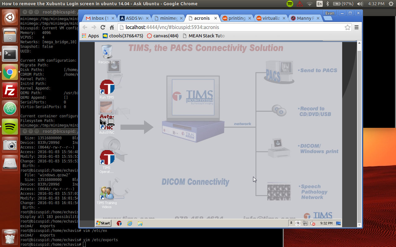
One of the device images we got from the radiology department is now up and running in a vm along with the pacs and a workstation(windows) vms. It looks like the radiology device is windows 7. Here’s what I did to get the the .tib file we got from radiology booted(with the list of wrong turns left out…).

  1. set up a windows partition on my laptop
  2. install the trial version of acronis snap deploy on the windows partition
    • acronis is the company whose software uses .tib files
  3. used acronis snap deploy to create a bootable acronis .iso
    • I’m still confused about what their .iso actually is. Did they make their own operating system to help people make copies of and restore windows computers???
  4. launched a vm in minimega with a windows qcow2 file as the disk and the acronis iso as the “cdrom”
    1. At this point the vm would boot to acronis but didn’t have a .tib file to set up
    2. I created a nfs folder on bicuspid that is available to the virtual hospital vms and put the .tib inside it
    3. told the vm to use the .tib file in the nfs folder
    4. At this point I was still getting errors, I expanded the qcow2 image that was the vm’s “disk” and then acronis was able to deploy the .tib to the vm. Now the vm appears to just be windows 7.

The picture below (the grey part) is what the radiology device vm looks like.

tims